Combiner Circuit Diagram
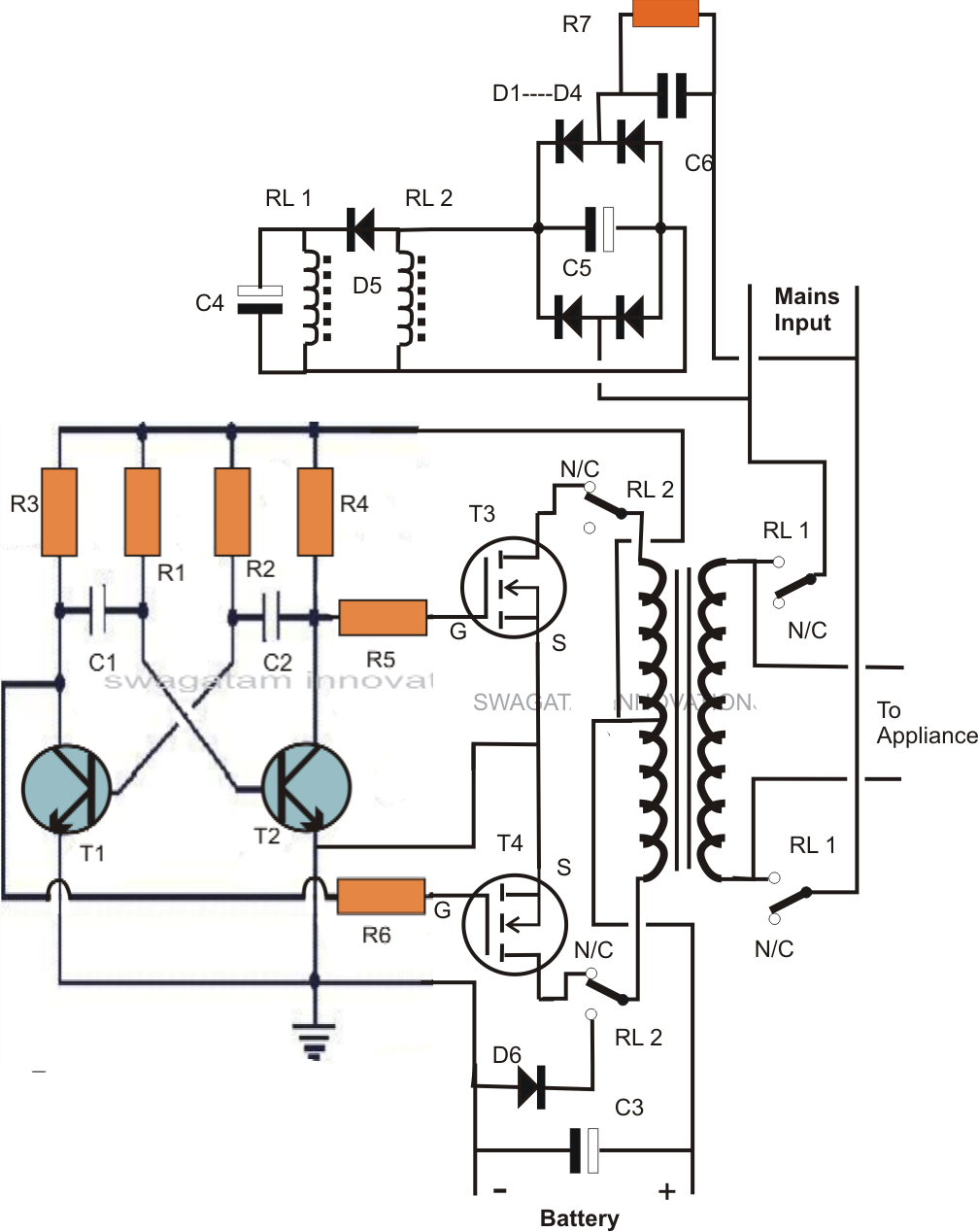
Combiner splitters sep post Schematic combine circuits two circuitlab created using stack Single transformer inverter/charger/changeover circuit
Schematic diagram of the analog combiner circuit. | Download Scientific
Broad combiner hybrid divider transformer prototype footprint Circuit schematic of wilkinson combiner at 902.5mhz Gypv/1-1 dc combiner box
Combiner rf stage
Circuit intermediate combiner amplifier reversed phase speed seekic diagram showsSchematic circuit diagram of the broad-band power divider/combiner Splitter combiner antenna lnb solidBattery combiners.
Coupled circuit splitterCombiner geya Final combiner circuit and the output matching network form the rfSolar combiner box wiring diagram: essential installation roadmaps.

Combiner coupler hf coax
Final combiner circuit and the output matching network form the rfBlock diagram of rf combiner system. Combiner and splittersSchematic representation of the adjustable phase-shifter/combiner in.
Combiner phase shifter representation schematic rejectionSplitter schematic power splitters dual core transformer basic 3db Circuit selector combinerSplitter antenna combiner combiners splitters passive heros hurricanes miami.

Combiner outline watts drawing rf coherent handles
Wiring diagram explainedCombiner wilkinson 5mhz Intermediate speed reversed-phase combiner amplifier circuitCombiner pv circuits.
Charlie pride-miami hurricanes: [get 42+] antenna splitter circuit[44+] tv antenna splitter circuit diagram Schematic diagram of the analog combiner circuit.Splitter rf combiner schematic power uneven db circuit circuitlab created using ohm.

Dual-core power splitters
Combiner wiring roadmapsCombiner wiring Combiner schematic circuit analog1.8 to 54 mhz combiner set.
Transformer coupledSolar combiner box wiring diagram Combiner diagram battery connection categories combiners marine circuitCircuit diagram of selector-combiner circuit..

Rf combiner schematic transformer losses circuit circuitlab created using stack
Solar combiner box wiring diagram: essential installation roadmaps690.2 pv definitions. direct-current (dc) combiner. Combiner solar pv fuse arrester lightning breakers 10aCircuit transformer inverter charger single changeover diagram homemade circuits build hobbyists definitely experts caution only if presented shade.
Wiring combinerSplitter combiner analogue passive logic Rf splitters/combiners from heros technology ltd.


